Wiring Information
If you need to check ECU or relay pinouts, this page should have all the info you'll need.
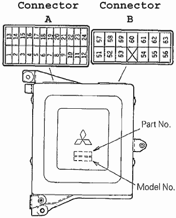
DSM ECU Pinout

Connector A (C-66) (Biggest)
| Pin |
Connection |
| 1 |
Self-Diagnosis Output (Y) |
| 2 |
Diagnosis/Data Transfer (W) |
| 3 |
Boost Gauge (BR) |
| 4 |
Oxygen Sensor (W) |
| 5 |
Power Steering Oil Pressure Switch (BY) |
| 6 |
Resistor in MAFS (GW) |
| 7 |
Air Conditioner Switch (BG) |
| 8 |
Intake Air Temperature Sensor (GO) |
| 9 |
Knock Sensor (W) |
| 10 |
Air Flow Sensor in MAFS (GL) |
| 11 |
ABS Control Unit (AWD, ABS Only) (RL) |
| 12 |
Ignition Timing Adjustment Connector (YR) |
|
| Pin |
Connection |
| 13 |
Control Relay (Fuel Pump Relay Control) (BW) |
| 14 |
Idle Switch (G) |
| 15 |
EGR temperature sensor (CA only) (LY) |
| 16 |
Barometric Pressure Sensor in MAFS (GY) |
| 17 |
Sensors Ground (GB) |
| 18 |
Vehicle Speed Sensor (YW) |
| 19 |
Throttle Position Sensor (GW) |
| 20 |
Coolant Temperature Sensor (YG) |
| 21 |
Crank Angle Sensor (RPM) (B) |
| 22 |
Top Dead Center Sensor (Cam Signal) (W) |
| 23 |
Sensor Power (+5v) (GR) |
| 24 |
Sensors Ground (GB) |
|
Connector B (C-65) (Middle)
| Pin |
Connection |
| 51 |
Cylinder 1 Injector (YG) |
| 52 |
Cylinder 2 Injector (YB) |
| 53 |
EGR Control Solenoid Valve (CA) (BY) |
| 54 |
Power Transistor for #1 & #4 Coil (Y) |
| 55 |
Power Transistor for #2 & #3 Coil (YR) |
| 56 |
Control Relay (Fuel Pump Control) (WR) |
| 57 |
Fuel Pressure Control Valve (W) |
| 58 |
Coil "A1" for ISC Servo (L) |
| 59 |
Coil "A2" for ISC Servo (Y) |
|
| Pin |
Connection |
| 60 |
Cylinder 3 Injector (Lg) |
| 61 |
Cylinder 4 Injector (LgW) |
| 62 |
Purge Control Solenoid Valve (BW) |
| 63 |
Control Relay Pin 8 (BL) |
| 64 |
Engine Warning Light (CEL) (RG) |
| 65 |
Air Conditioner Relay (RL) |
| 66 |
Control Relay Pin 8 (BL) |
| 67 |
Coil "B1" for ISC Servo (W) |
| 68 |
Coil "B2" for ISC Servo (B) |
|
Connector C (C-64) (Smallest)
| Pin |
Connection |
| 101 |
Ground (B) |
| 102 |
Power (+12V) (R) |
| 103 |
Backup Power (+12v) (BR) |
| 104 |
Inhibitor Switch (A/T) / Ground (M/T) (B) |
| 105 |
Wastegate Solenoid (O) |
|
| Pin |
Connection |
| 106 |
Ground (B) |
| 107 |
Power (+12V) (R) |
| 108 |
Ignition Switch - ST terminal (start signal) (BY) |
| 109 |
Ignition Pulse Detect (Tach) (W) |
| 110 |
Ignition Switch - IG terminal (on signal) (BW) |
|
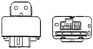
DSM Main (Control) Relay
| Pin |
Connection |
| 1 |
No Connection |
| 2 |
Fuel Pump (BG) |
| 3 |
Ignition (BW) |
| 4 |
Power (+12V) (R) |
| 5 |
Power (+12V) (R) |
|
| Pin |
Connection |
| 6 |
Ground (B) |
| 7 |
ECU pin 56 (Fuel Pump Signal) (WR) |
| 8 |
ECU pin 63 and pin 66 (BL) |
| 9 |
Starter Signal (BY) |
| 10 |
Constant +12 V Power Supply (R) |
|
Starion ECU Pinout

Connector A (B-37) (Yellow)
| Pin |
Connection |
| 1 |
Engine Speed Sensor ( IGN Coil (-) Terminal) (W) |
| 2 |
Air Flow Sensor (WB) |
| 3 |
Motor Position Sensor (LR) |
| 4 |
Sensor Ground (B) |
| 5 |
Intake Air Temperature Sensor (GR) |
| 6 |
Coolant Temperature Sensor (YG) |
| 7 |
Idle Switch (YR) |
| 8 |
No Connection |
| 9 |
No Connection |
| 10 |
Sensor Power (+5V) (GR) |
| 11 |
Oxygen Sensor (W) |
| 12 |
ISC Servo (for retraction) (YB) |
|
| Pin |
Connection |
| 13 |
Ignitor Advance Control Signal (YB) / Test Connector (RY) |
| 14 |
Sensor Power - MPS Backup (LY) |
| 15 |
Throttle Position Sensor (GW) |
| 16 |
Barometric Pressure Sensor (BW) |
| 17 |
No Connection |
| 18 |
No Connection |
| 19 |
Vehicle Speed Sensor (LgB) |
| 20 |
Secondary Air Control Solenoid Valve (RG) |
| 21 |
Diagnosis Output (BR) |
| 22 |
Control Relay (Fuel Pump Relay Control) (WR) |
| 23 |
ISC Servo (for extension) (YL) |
| 24 |
Air Conditioner Power Relay (??) |
|
Connector B (B-36) (Green)
| Pin |
Connection |
| 51 |
Power (+12V) (R) |
| 52 |
Ground (B) |
| 53 |
Ground (B) |
| X |
|
| 54 |
EGR control solenoid valve (RW) |
| 55 |
Ignition Switch - ST terminal (start signal) (BY) |
| 56 |
Air Conditioner Switch (BW) |
|
| Pin |
Connection |
| 57 |
Power (+12V) (R) |
| 58 |
Inhibitor Switch (A/T) / Ground (M/T) (BY) |
| 59 |
Boost Gauge (YG) |
| 60 |
Injector 1 (Primary) (YB) |
| 61 |
Knock Sensor (Br) |
| 62 |
Injector 2 (Secondary) (YL) |
| 63 |
Backup Power (+12V) (RB) |
|
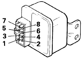
Starion Main (Control) Relay (B-30)
| Pin |
Connection |
| 1 |
Fuel Pump (BW) |
| 3 |
Injector Power (BR) |
| 5 |
ECU pin 52 (Ground) (R) |
| 7 |
Battery +12 V Direct (20A Fused) (B) |
|
| Pin |
Connection |
| 2 |
ECU pin 22) (Fuel Pump Signal) (WR) |
| 4 |
Ground (B) |
| 6 |
Ignition Switch - ST terminal (start signal) (BY) |
| 8 |
Ignition Switch - IG terminal (on signal) (L) |
|
© 2012 Cybernetics


