|
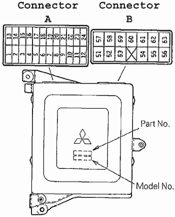
'88 Starion ECU pinout
|
| |
The colors DO NOT represent wire colors.
The colored wires are, however, important for the motor swap.
This info was found in the Starion FSM (14-11).
|
|
|
 |
|
|
|
Connector A (Yellow)
| Pin |
Connection |
Pin |
Connection |
| 1 |
Engine Spd: IGN Coil
Neg Terminal |
13 |
Ignitor advance |
| 2 |
AFS |
14 |
Sensor +5 backup |
| 3 |
Motor position SW |
15 |
TPS |
| 4 |
Sensor GND |
16 |
Barometric sensor |
| 5 |
Intake temp |
17 |
n/c |
| 6 |
Coolant temp |
18 |
n/c |
| 7 |
Idle SW |
19 |
Speed (coil) |
| 8 |
n/c |
20 |
secondary air
(catalyst) |
| 9 |
n/c |
21 |
Diag. Output |
| 10 |
+5 volt power |
22 |
control relay (fuel pump) |
| 11 |
O2 sensor |
23 |
ISC + (out) |
| 12 |
ISC – (in) |
24 |
AC relay |
|
|
|
|
Connector B (Green)
| Pin |
Connection |
Pin |
Connection |
| 51 |
+12
V |
57 |
+12
V |
| 52 |
GND |
58 |
inhibitor switch
(A/T) |
| 53 |
GND |
59 |
Boost gauge
|
| X |
|
60 |
Injector 1 (primary) |
| 54 |
EGR |
61 |
Igniter signal (Knock
Sensor) |
| 55 |
IGN
(cranking) ST signal |
62 |
injector 2
(secondary) |
| 56 |
AC switch
|
63 |
+12
V backup |
|
|
|
|
 |
|
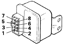
Main (Control) Relay
| Pin |
Connection |
Pin |
Connection |
| 1 |
Fuel Pump |
2 |
ECU |
| 3 |
Resistor |
4 |
GND |
| 5 |
ECU |
6 |
IGN
(cranking) ST signal |
| 7 |
Battery +12 V direct (20A fused) |
8 |
Ignition switch (IG) |
|
|
|
|
|
|