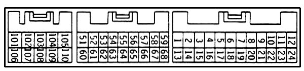
::Project 0G::

'90 DSM ECU pinout

 
 The colors DO NOT represent wire colors.  The colored wires are, however, important for the motor swap.  This info was found in the DSM FSM.  The differences between the later 1G ECU's pinouts is only that Pins 6 and 14 are switched.  You don't have to touch any of this so don't worry about that.


Connector A (Biggest)

Pin Connection Pin Connection
1 Self-Diagnosis Output 13 Control Relay (Fuel Pump Signal)
2 Diagnosis/Data Transfer 14 Air flow Sensor Active Filter Reset
3 Turbo Meter 15 EGR temperature sensor (CA only)
4 Oxygen Sensor 16 Barometric pressure sensor
5 Power Steering Oil Pressure Switch 17 Sensors GND
6 Idle Position Switch 18 Vehicle Speed Sensor
7 Air Conditioner Switch 19 Throttle Position Sensor
8 Intake Air Temperature Sensor 20 Coolant Temperature Sensor
9 Detonation Sensor 21 Crank Angle Sensor (RPM)
10 Air Flow Sensor 22 Top Dead Center Sensor
11 n/c 23 Power Supply for Sensors (5v)
12 Ignition Timing Adjustment Con. 24 Sensors GND

Connector B (Middle)

Pin Connection Pin Connection
51 No. 1 Injector 60 No. 3 Injector
52 No. 2 Injector 61 No. 4 Injector
53 EGR Control Solenoid Valve (CA) 62 Purge Control Solenoid Valve
54 Power Transistor for #1 & #4 63 Control Relay
55 Power Transistor for #2 & #3 64 Engine Warning Light (CEL)
56 Control Relay (Fuel Pump Control) 65 Air Conditioner Relay
57 Fuel Pressure Control Valve 66 Control Relay
58 Coil "A1" for Edle Speed Ctrl Servo 67 Coil "B1" for Idle Speed Ctrl Servo
59 Coil "A2" for Idle Speed Control 68 Coil "B2" for Idle Speed Ctrl Servo


Connector C (Smallest)

Pin Connection Pin Connection
101 GND 106 GND
102 Power Supply 107 Power Supply
103 Constant Power Supply For Backup 108 ST
104 Inhibitor Switch (MT) 109 Ignition Pulse Detector
105 Wastegate Solenoid 110 "1G" Terminal for Ignition Switch
 

Main (Control) Relay

Pin Connection Pin Connection
1 n/c 6 GND
2 Fuel Pump 7 ECU (13)
3 IGN 8 ECU (63)
4 Power Supply 12V to Sensors 9 ST
5 Constant +12V Power Supply 10 +12V Switched Power